Monday, December 14, 2009

Individual Reflection by: Michael DiCenso

This semester in ME250 was a complete success. We learned skills ranging from design and manufacturing to teamwork to time management. These aspects are key to becoming a well-rounded engineer.

Transforming our dreams and designs into reality in our complex robot was very enjoyable. It is amazing watching scrap being turned into a masterpiece. However, this transition from design to the actual manufacturing was also very difficult. I learned that you have to make sure that the all the tolerances on every dimension of a part is consistent, otherwise the other pieces may not mate well or you may add damaging stress or strain to your machine, including unneeded friction. For example, we don’t exactly know the reason why our chassis wouldn’t drive straight, but I believe it is because our tolerances were too small on the holes and alignment of the axles in the bushings to the double gearbox. The slightest misalignment could cause too much friction to build up in the bushing, therefore causing there to be too much strain on the gears in the double gearbox. This most likely on happened on one side, causing it to turn in the same direction every time. Another obstacle that was hard on our group’s manufacturing process was the fact that we weren’t thinking of how difficult it would be to actually make some parts in the machine shop when we were designing them. The foot (wedge) of our arm was the most difficult piece for me to manufacture. We had to make sure that our arm wasn’t too heavy, or else we would have to change the gear ratio needed to move it. We thought of making the arm out of different metals and even different types like sheet metal or square stock. Our final decision was to stick to the original plan of making it out of the solid aluminum block, but I had to be perfect on my measurements during manufacturing. Long story short is that it took close to two and a half hours to make this one piece using the consistency and preciseness of the milling machine. This piece and others like it, with the same problem of the simplicity of manufacturing, took way too much of our team’s time putting us in a rush to finish toward the deadline.

Another aspect of this class was the point of working as a team and all collaborating together as a group to achieve the same goal. Thankfully I was blessed with a great bunch of extremely bright guys that made brainstorming a breeze. We could easily come up with ideas to solve problems and get the job done. Unfortunately my team didn’t really have much machine experience (other than Andrew and me) but like in all aspects of the project, if someone struggled with a skill, someone else was there to excel in what was required. Dylan was great with solidworks while Chan was a genius with the analysis, leaving me and Andrew to be masters in the shop. We were all there to help each other, but the problem with our group was finding time for all of us to meet. The fact that I live on central campus while the others live on north campus and that all of us have completely different schedules and commitments made it very difficult for us to come together. This made time management very crucial, and while, looking back, there was room for improvement, but we managed to finish the project on time and met expectations.

For the future, I believe this class, as a whole, should make a few changes. First off, the workload of the semester was a nightmare. At points in the year, I thought I was in an eight credit hour class due to the number of homework assignments and the time period to do it all. Seeing that previous years made model computer mouses and cup holders, some of the assignments (although helpful to our understanding of technology and informative about some of the basic requirements of an engineer) should have been cut from the curriculum due to the length of the semester. Overall, despite hating it at certain, stressful points, I enjoyed the class and what we learned was very interesting.

Final Bill of Materials and More Photos from Team Pending

Here we are, drawing to a close, a semester of planning and building. Here are a few photos from over the semester showing the progress of our machine from ground up to completion. Be sure to read Andrew's whole overview of the final Machine below, including our disheartening defeat at the hands of team Thunder and Lighting. It was great to see the machine come from concept to physical form over just a few short weeks, and I can say I really proud of the way that we managed to bring everything together in the end.

Our final Bill of Materials can be found Here. The total for the parts bought in addition to the kit came to $41.36, putting the total cost of components at $136.66.

Finally, enjoy some pictures of the machine and competition from the last few weeks. I also have uploaded a few pictures of other teams from our lab section, too.


Semester Reflection: Dylan Box

I was glad to be part of a Design-Build-Test class as my first foray into my Mechanical Engineering degree. Throughout the last semester, I have gained a great variety of skills, like advanced CAD modeling, material selection, drawing creation, machining techniques, and assembly methods. While I have used the Design-Build-Test method in various other settings like the Odyssey of the Mind club and prior classes, it was very important to work as engineers in the field actually do: relying on component drawings and planned machining techniques rather than “winging it” as previous classes have often been conducted. It is important to note, that while it is nice to have a complete plan-of-action, when problems arose, our team was there to improvise and solve problems, another very important skill that can only really be learned in a hands on setting such as this. But despite glitches and hiccups along the way, the knowledge gained became vital to the completion of our final project.
The most important part of this class to me was to learn about various engineering principles outside of abstract learning environments. Having bike and motor labs were very helpful to the understanding of concepts discussed in class, such as gear trains and linkages; I like to see the inner-workings of these everyday devices in a learning setting. However, I would have liked some extra time to work and schedule these sessions. In general, required outside work time needs to be scheduled far in advance (at least a week ahead), rather than the two-to-three day noticed we received about the Bike and Motor labs, as I had difficulty scheduling around my eighteen credit-hours and job on such short notice. Apart from the extra lab sessions, I appreciated detailed information regarding mechanical components, rather than only abstract concepts regarding purely dynamics. Due to my degree in Art & Design and Engineering, I find that most of my work will be done designing mechanical systems using these components and less time dealing with intangible concepts, which I am often bombarded with in the engineering school.
Also apart vital to the study of engineering is the element of team or group work. One would be hard-pressed to find an engineering job where teamwork is not necessary, and so requiring hands-on, teamwork experiences to students is vital to the job market later on. Again, utilizing my prior experience with teams, clubs, and classes, working with a team was not far outside of my comfort zone. However, to utilize this group mentality, it would be nice to see more assignments that required a variety of experience and skill sets, as some weeks I could find myself stuck being the only one who knew how to use Solidwork, which could compose the majority of a homework assignment. Time-management in a group setting also became an important issue. Working with so many different schedules on out of class time was often extremely difficult. I think that more delgation and better communication within our group could have greatly improved how our machine came together of the few weeks. It would also be nice to get started on the project sooner (a combination of a slow-to-start attitude from our team and a front-loaded class schedule, were to blame this term). In future sessions, more focus on engineering processes and less on calculations (often done in classes like ME240 and Physics 140 and 240) would be nice, and would allow the class to move quickly through the concepts and get into the hands-on experience, where those concepts can be cemented for future use.
Overall, I found myself learning a great deal about engineering and mechanical processes and concepts that I will certainly use throughout the rest of my education and career. Despite an enormous time-commitment, the class went rather smoothly, and I was happy with our final product, even though we did not win. From previous semesters, it seems that this class has undergone an important and helpful shift, and it is not far off from being fully ironed out. Most importantly, in further iterations of this class, outside of class homework and projects needs to be considered. I personally spent more time on this class than any of my others classes combined, and for only a four-credit course out of an eighteen-credit schedule, it was rather unreasonable. I would recommend the class focus more on the “Design and Manufacturing” process as indicated by the course syllabus and title, and less re-hashing of concepts learned in other required ME classes. I look forward to seeing where this class is going in the future, and to seeing how what I have learned here will impact me later on in my career.

Sunday, December 13, 2009

Reflection of ME 250 by Chan

From my experience of a semester of ME 250, the class turned out to be extremely different from what I had expected. This statement expresses both my positive feedbacks of the class and my frustration and disappointment of the class.
First, I truly believe that ME 250 demonstrates what an engineer does in the real industrial world, and the class works as a strong motivator and a preview of one side of a future for all mechanical engineer students. It clearly gives a view of the process an engineer takes to apply their creative ideas, into a realistic strategy, concept, and machinery. I further believe that the class did an exceptionally good job in teaching the manufacturing part of the program. I personally have learned to lathe, and now I feel no trouble in assembling, performing, and disassembling the different tools used in the lathing machine. I have also learned to change different speeds in the drilling machine, and the use of a milling machine. In general I really had fun in creating my own machine with different materials provided.
The factor that disappointed me the most about the class was the inconsiderate planning of the course schedule and the outrageous amount of work load. Many times during this semester, ME 250 class gave me the impression that it failed to recognize the fact that students are also taking other classes. The first part of the semester was a nightmare, keeping most of the student awake during Saturday and Sunday nights with lecture homework, Lab assignments and CAD assignments. Many times I had to pull an all nighters, sleeping around 6 in the morning. Furthermore, the class took way too much time out of class. For example, having the bicycle meeting with GSI on the day of Thanksgiving break was unreasonable. I also had to miss many of other class time because of the presentation of MS assignment on Friday. (This was the only day where everyone else was free.) Presentation of MS assignment should have been done during lecture time, or in the lab with GSI. (I guess always being pressured by time in this class taught me how to manage my times better.)
In a team, I learned that many people have different ideas, and they all have their own point of view. I learned that people tend to be stubborn with their own ideas and do not take changes by others very well. I learned how to manage my schedule so to fit the team’s meeting times and that sometimes many sacrifices are needed.
I personally believe that our team would have done so much better if we were more persistent, and placed more effort on our machine in our final manufacturing. I further believe we would have created a better effect if all the members worked more efficiently as a team. It was truly hard to find a time where everyone of the team was in a single meeting. I also believe that if we started to manufacture a bit faster, it would surely have given us more time to test and make adjustments which would have definitely increased our performance.
In general, I had very much fun in this class, manufacturing and placing different parts together, and seeing them work with each other gave me the thrill I have felt in a long time. I also had fun meeting new people in the lab, and seeing how other’s having put their ideas in to play. It was fun to see how a common ground such as ME 250 can bring different people together, and that includes the GSI.

Team Wrap Up by Andrew Kelner

Well we've finished the competition and I thought I would give a brief wrap up. Although our machine lost in the first round to team Thunder and Lightning I thought our design was solid and that with some luck we could have done much better in the competition. Our machine was made from a housing made of wood which we lasercut and put teeth in and then epoxied together. The arm of the machine was placed in the center groove of the housing and was controlled by a rack and pinion device run by one of the planetary gearboxes and constrained by several wheels. The lower arm held attached the upper arm to the wedge and had the plate through which the Kevlar thread was placed (originally where the fisheye hooks were). The wedge was moved up and down by Kevlar thread attached to a spool and powered by another planetary gearbox. The machine itself was powered by a double gearbox that was mounted in the center of the machine and drove the two front wheels. The double gearbox axles were connected to the front wheel axles by .25in diameter tubing and zip ties. Faulty zip ties may be why the machine didn't drive straight (see my final thoughts write up for more details). All in all I thought the machine was very solid and did a great job of competing in the arena. With a little more time to iron out the kinks I think it would've even had a chance at winning. See my final write up (below) for a more in depth look at our final machine and pictures.
-Andrew Kelner

The Results Are In - A Final Comment by Andrew Kelner


Well we've done it, as a team we Team Pending have completed the ME250 course and competed with our finished robot in the arena. Although we did not do as well as I would've hoped (We lost in Round One to team Thunder and Lightning) I do think that the machine was overall very solid. This course has been quite the experience, from the early design stages and narrowing down from strategies all the way to individual components, to the actual fabrication of our machine, this class has tested both my design creativity and my ability to take those ideas and actually create a physical interpretation of them. Going back to our machine I think that the team as a whole was very good at taking the concept and strategy and making our idea really come to life. I will say that there were a few bumps along the way. From having to do a lot of fabrication of the body on the laser cutter (parts that were originally planned to be made of aluminum) to trouble with getting the machine to drive perfectly straight, we had our fair share of problems. I do however, think that most of these were ironed out when we got a chance to test our robot for a few days and see what extra things were necessary (such as the epoxying of the entire body and the aluminum plate that was added to the arm to push the kevlar thread out so that the wedge wouldn't get stuck). I think that the plate that was added to the arm to push the thread out was a great help. Before adding it when the wedge was lowered all the way down and the thread tried to raise it again, the wedge would get stuck because the thread would be pulling straight up rather than diagonally. With the plate on the arm it helped to push the thread out and keep it at an angle so that it would always be able to pull the wedge up. If I were to do anything differently on the machine I would have probably tried to start the fabrication sooner. With more time we would have had more testing and as a result more time to fix some of the problems we found with our machine. One problem we found was that the machine had trouble driving in a straight line. Whether this was due to lack of lubrication within the double gearbox, problems with the motors or resistance in the wires, or a faulty connection of one of the tubing pieces connecting the gearbox axle to the axle of the wheel, we do not know. We tried extensively to fix all of these problems but to no avail. My only guess can be that it was a faulty tubing connection that only manifested itself under high torques. With more time I think we would have been able to fix this problem and as a result have done better in the competition. Regardless of this I think that the machine turned out well overall and would like to thank the other members of Team Pending for their contributions to the finished product. Many Thanks to Dylan Box, Mike Dicenso, and Chan Woo Kim, as well as Professor Hart and Sei Jin Park and the rest of the ME250 staff. I really enjoyed this class and think that the skills and knowledge of the design process I have learned will help me not only during the rest of my time at Michigan, but at future jobs as well.
-Andrew Kelner

Wednesday, December 9, 2009

Sunday, December 6, 2009

The Final Push

Team Pending spent a lot of time in the lab over the past week and we got a ton accomplished. This weekend we finished assembling the machine and have begun testing. A couple of design tips for your next big project. If you want to make a toothed wooden box like ours for a chassis, make sure the dimensions of the teeth are the same as the width of the board. We choose a .25" thick piece of plywood as material, which requires .25"x.25"x.25" teeth. Laser Cutting the teeth is really the best method, as hand cutting those can be inaccurate (making the box difficult, if not impossible, to assemble) and time consuming. We found the best setting for the laser cutter (on a 50 watt bulb) to be 50% power and 1.4% speed. If you are looking to get really intense and secure, look into the dovetail cut, as it will be far more sturdy, but very difficult to make (you can't do it on a laser cutter). Here's a few pictures of our assembly in-process:


Sunday, November 29, 2009

Final CAD Model Pictures

In addition to the work done (as Chan described in today's post), we also finished the CAD model of the machine. Here's a few pictures:

Top:

Side:

Front:

Detail of box cut pattern:

Finalize Manufacturing of MCM

Our group were able to completely manufacture the different parts of the MCM(arm of the robot), and assemble them together to demonstrate it's function. This week, we spend time in creating the spool, and the wedge of the MCM, both crucial parts in the arm's working process.

With the 1" diameter by 12" length aluminum cylinder that Dylan order last week, we began to create our spool. First we started off by lathing the spool in to the correct diameter. On Monday the 23rd we were able to create the thin cylindrical axle for the spool, but had to stop there due to lack of time. On the following day we finished off the spool by lathing off the inner part. This inner part was to be used for curling up the threads and making the wedge become horizontal as the spool rotates. When the cylinder was lathed into correct dimension, we cut the rest of the unwanted cylinder off with the Bandsaw. We finished off the spool by drawing a tiny hole through the outer circle of the spool head (not the axle). The thread was placed through this tiny hole and was tied up.

In the case of the wedge, we first had to cut the 1"x1"x12" square aluminum stock in to the dimension needed, and then we used the milling machine to shape it into a wedge shape designed as our Solidworks engineering drawings. When all the milling process was complete, we drilled the two parallel holes that will be connected to our Joining arm, which was manufactured previously. The wedge was then filed and polished by using a hand-file and sand paper. When we created the wedge, it gave us a small impression that we might have to reconsider the size of the wedge, since it was smaller than what we expected.

Further constrains for the gear and the axle of the spool were created by simply cutting and drilling the right angle aluminum. Then the ball bearings and the bushing were placed into the holes by press-fitting them.

When all our parts for the MCM was completed, we assembled them and connected them together with bolts that Andrew ordered.

Monday, November 23, 2009

Continued Manufacturing of MCM

For the past week we have been working on the manufacturing of our Most Critical Module. Dylan ordered an 1"x1"x12" square aluminum stock and a 1" diameter by 12" length aluminum cylinder so that we could manufacture our wedge and our spool for the arm winch. Friday afternoon we finished making the upper arm and press fit in the rack, the lower arm, and the axle for the winch. On Monday (11/23, we plan to manufacture the wedge. There will be an update soon with pictures.

Monday, November 16, 2009

Start of Manufacturing

For the past week, we worked on the manufacturing of three parts(components). We decided to start with our most critical module, the arm.


For the first part, we took the 1" x 1" hollow aluminum tube stock and cut it to 18" in length. Next we drilled two .25" holes near the bottom of the piece that will be used to mate the two pieces of the arm. This will be the upper arm .


Next we took the .5" x .5" square aluminum tube stock and drilled two .25" holes on one side to mate with the upper arm and a one more .25" hole on the opposite side to mate with the wedge foot.

We are currently in the process of ordering the medal for the wedge foot from McMasters.


For the third part, we took the .25" aluminum rod and cut it to 5". This will be the axle that is attached to the gear for the rack and pinion.

.

Sunday, November 8, 2009

Updated CAD Model

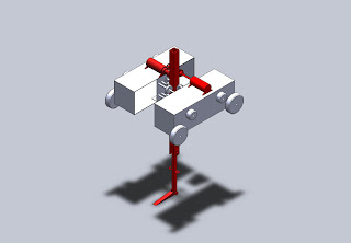
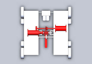
For MS6, the Most-Critical Module assignment, we updated and fixed our CAD model, adding some new components and solving the issue of constraint. Instead of single wheels on each side of the arm, the new model has two wheels on three of the sides and 2 gears on the back side. By constraining it in two places on every face, we limit the degree of freedom to the one, vertical, axis. We also altered the wedge in order for it to fit with our more recent machining strategy.

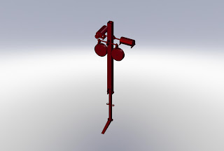
In the photos, you will notice our most critical module, the arm, is highlighted in red.

Fig. 1 Isometric View of Assembly


Fig. 2 Front View of Assembly


Fig. 3 Top View of Assembly

Thursday, October 29, 2009

Design for Team Pending

Our design combines a moving chassis with workable arm in order to move the Ping Pong Balls in a manner that is not dependent on a perfect circumstance. The machine has a arm with a wedge that lowers into the tank and flips out to form a platform for lifting the PPBs. The arm moves up and down on a rack and pinion moved by a planetary gearbox and is constrained by sets of wheels to limit the motion to one degree of freedom. The wedge is flipped out by a winch attached to another planetary gearbox. The machine can then move over to the wall and lift the PPBs over and onto the opponent's side. The chassis movement is provided by the Tamiya double gearbox which is connected to a set of 4-wheel treads. The treads increase the friction between the table and the machine, which will help stop the opponents from moving and forcing our machine.

The preliminary CAD model of the assembly


CAD model of the arm module


CAD model of the chassis module

Schedule for Team Pending

schedule