Hope you enjoy!
Wednesday, December 9, 2009
Sunday, December 6, 2009
The Final Push
Team Pending spent a lot of time in the lab over the past week and we got a ton accomplished. This weekend we finished assembling the machine and have begun testing. A couple of design tips for your next big project. If you want to make a toothed wooden box like ours for a chassis, make sure the dimensions of the teeth are the same as the width of the board. We choose a .25" thick piece of plywood as material, which requires .25"x.25"x.25" teeth. Laser Cutting the teeth is really the best method, as hand cutting those can be inaccurate (making the box difficult, if not impossible, to assemble) and time consuming. We found the best setting for the laser cutter (on a 50 watt bulb) to be 50% power and 1.4% speed. If you are looking to get really intense and secure, look into the dovetail cut, as it will be far more sturdy, but very difficult to make (you can't do it on a laser cutter). Here's a few pictures of our assembly in-process:


Sunday, November 29, 2009
Final CAD Model Pictures
In addition to the work done (as Chan described in today's post), we also finished the CAD model of the machine. Here's a few pictures:
Top:

Side:

Front:

Detail of box cut pattern:

Top:

Side:

Front:

Detail of box cut pattern:

Finalize Manufacturing of MCM
Our group were able to completely manufacture the different parts of the MCM(arm of the robot), and assemble them together to demonstrate it's function. This week, we spend time in creating the spool, and the wedge of the MCM, both crucial parts in the arm's working process.
With the 1" diameter by 12" length aluminum cylinder that Dylan order last week, we began to create our spool. First we started off by lathing the spool in to the correct diameter. On Monday the 23rd we were able to create the thin cylindrical axle for the spool, but had to stop there due to lack of time. On the following day we finished off the spool by lathing off the inner part. This inner part was to be used for curling up the threads and making the wedge become horizontal as the spool rotates. When the cylinder was lathed into correct dimension, we cut the rest of the unwanted cylinder off with the Bandsaw. We finished off the spool by drawing a tiny hole through the outer circle of the spool head (not the axle). The thread was placed through this tiny hole and was tied up.
In the case of the wedge, we first had to cut the 1"x1"x12" square aluminum stock in to the dimension needed, and then we used the milling machine to shape it into a wedge shape designed as our Solidworks engineering drawings. When all the milling process was complete, we drilled the two parallel holes that will be connected to our Joining arm, which was manufactured previously. The wedge was then filed and polished by using a hand-file and sand paper. When we created the wedge, it gave us a small impression that we might have to reconsider the size of the wedge, since it was smaller than what we expected.
Further constrains for the gear and the axle of the spool were created by simply cutting and drilling the right angle aluminum. Then the ball bearings and the bushing were placed into the holes by press-fitting them.
When all our parts for the MCM was completed, we assembled them and connected them together with bolts that Andrew ordered.
Monday, November 23, 2009
Continued Manufacturing of MCM
For the past week we have been working on the manufacturing of our Most Critical Module. Dylan ordered an 1"x1"x12" square aluminum stock and a 1" diameter by 12" length aluminum cylinder so that we could manufacture our wedge and our spool for the arm winch. Friday afternoon we finished making the upper arm and press fit in the rack, the lower arm, and the axle for the winch. On Monday (11/23, we plan to manufacture the wedge. There will be an update soon with pictures.
Monday, November 16, 2009
Start of Manufacturing
For the past week, we worked on the manufacturing of three parts(components). We decided to start with our most critical module, the arm.

For the first part, we took the 1" x 1" hollow aluminum tube stock and cut it to 18" in length. Next we drilled two .25" holes near the bottom of the piece that will be used to mate the two pieces of the arm. This will be the upper arm .

We are currently in the process of ordering the medal for the wedge foot from McMasters.

.

Next we took the .5" x .5" square aluminum tube stock and drilled two .25" holes on one side to mate with the upper arm and a one more .25" hole on the opposite side to mate with the wedge foot.
We are currently in the process of ordering the medal for the wedge foot from McMasters.

For the third part, we took the .25" aluminum rod and cut it to 5". This will be the axle that is attached to the gear for the rack and pinion.
.
Sunday, November 8, 2009
Updated CAD Model
For MS6, the Most-Critical Module assignment, we updated and fixed our CAD model, adding some new components and solving the issue of constraint. Instead of single wheels on each side of the arm, the new model has two wheels on three of the sides and 2 gears on the back side. By constraining it in two places on every face, we limit the degree of freedom to the one, vertical, axis. We also altered the wedge in order for it to fit with our more recent machining strategy.
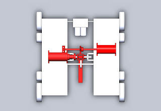
In the photos, you will notice our most critical module, the arm, is highlighted in red.
Fig. 1 Isometric View of Assembly
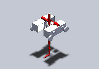
Fig. 2 Front View of Assembly

Fig. 3 Top View of Assembly
In the photos, you will notice our most critical module, the arm, is highlighted in red.
Fig. 1 Isometric View of Assembly

Fig. 2 Front View of Assembly

Fig. 3 Top View of Assembly

Subscribe to:
Posts (Atom)